
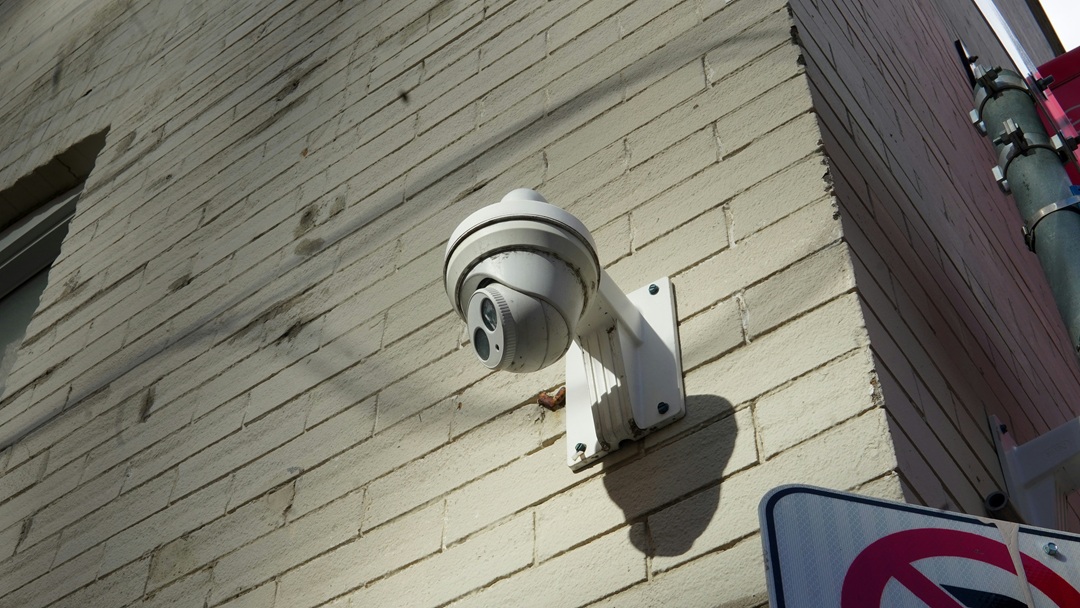
An outdoor PoE CCTV installation often involves more than running an Ethernet cable from a switch to a camera. Some connections may follow exterior walls, others may pass through conduits or underground routes, while longer cable runs must also deliver enough power to the camera at the far end.
For installers and security system integrators, cable selection therefore involves several project-specific considerations. The cable must suit the installation environment, support the required data transmission, and maintain adequate electrical performance over the planned distance.
Choosing between Cat5e and Cat6 is only one part of the decision. The cable jacket, conductor construction, DC resistance, route length and total number of camera connections all need to be considered before finalizing the project specification.
Planning the Cable Route and the Outdoor Construction
In a centralized PoE CCTV installation, each camera normally has its own cable run back to a PoE switch or a PoE-capable port in an equipment cabinet. That single cable carries both the data link and the DC power for the camera. A site with 24 cameras therefore means 24 separate runs. Each has its own route, its own length and its own exposure. Estimating material from the camera count alone assumes all 24 are alike, which is rarely the case around a building perimeter or across a parking area.
Drawing those routes on the plan comes before choosing a construction. A cable clipped along an exterior wall sees sunlight and weather for its whole service life; one pulled through an underground duct sees standing water and condensation instead; a direct-burial cable has to carry its own mechanical protection. Treating the three as variants of the same order line is where most mixed-site specifications go wrong.
| CCTV cable route | Main specification considerations |
|---|---|
| Exposed along exterior walls | UV and weather resistance of the jacket; mechanical protection where the run can be reached or struck |
| Through outdoor conduits or trays | Moisture and condensation in the conduit, water accumulation, pull tension and bend radius over long pulls |
| Underground, inside a duct | Water-blocked construction for a wet duct; the duct itself carries the mechanical protection |
| Direct burial | A cable specifically rated for direct burial, with armour or other protection matched to soil, stone and vehicle loading |
Polyethylene is commonly used for outdoor cable jackets because it handles weather and UV exposure well. It does not follow that a PE-jacketed cable is waterproof, rated for direct burial, or resistant to impact from trench backfill. Those properties come from the cable’s complete construction and its stated rating, not from the jacket material on its own. The outdoor cable constructions guide sets out how jacket, core and mechanical protection differ between aerial, duct and burial designs, so this article does not repeat that detail.
Water exposure is the part most often flattened into a single “outdoor” requirement. Condensation in a surface conduit, standing water in an underground duct and prolonged soil contact are different conditions, and a cable specified for one is not automatically specified for another. The project documents should name the water-blocking construction required for each route section instead of asking for a generic outdoor cable. Underground duct and direct burial are separate applications for the same reason: the first assumes a protective duct, the second assumes there is none.
Power Delivery and the Cable Specification
Distance affects a CCTV cable run in two ways at once: the Ethernet channel has a transmission limit, and the camera has a minimum operating voltage. For standard balanced twisted-pair cabling, 100 m is the commonly used maximum channel length, measured from switch port to device and including the patch cords at both ends. The permanent link — the fixed cabling installed in the building — is shorter than the channel, so a 90 m permanent link leaves a 10 m allowance for cords in total. Neither figure guarantees that a camera near the limit will receive enough power. They are separate checks against the same run.
Voltage drop is set by the resistance of the conductor path and the current the camera draws, so the electrical specification matters as much as the category. Resistance rises with length and with temperature, falls with a larger conductor cross-section, and depends on the conductor material. Bundled cables heat one another, which raises resistance again. The PoE cable guide covers how current, bundle size and installation conditions interact; for a CCTV project the practical consequence is that the longest, warmest and most heavily bundled run is the one to check; an average figure gives no useful answer.
Camera load varies more than a category label suggests. A fixed camera drawing modest power is a different electrical case from one with infrared illumination, a heater or PTZ drive, particularly at low ambient temperatures when those loads may coincide. Treat the camera’s specified power requirement as an input to the cable calculation here, not as a reason to reopen camera selection. Where a project mixes camera types, the highest-load run on the longest route is the one that sets the specification.
That is why category alone cannot settle the purchase. Cat6 does not automatically deliver power better than Cat5e in every product configuration: two cables carrying the same category print can differ in conductor material, conductor diameter and measured DC resistance. A Cat5e cable on solid copper at 23 AWG and a Cat6 cable built to a different conductor specification are not electrically equivalent simply because both are rated for their category. The copper or CCA comparison explains why conductor material and finished-cable test evidence are separate questions; for procurement, ask for the conductor specification and resistance data rather than inferring them from the printed category.
| Parameter | What to confirm |
|---|---|
| Conductor material | Bare copper or another stated conductor material, with evidence for the specific product |
| Conductor size | AWG and actual conductor diameter, not only the category |
| DC resistance | Measured resistance and the conditions it was measured under |
| Cable length | Planned route length for each camera, including slack and installation allowance |
| PoE load | The connected camera’s specified power requirement |
| Installation condition | Ambient temperature range and expected bundle size along the route |
No universal PoE distance can be derived from Cat5e or Cat6 alone. For an actual project, power delivery has to be evaluated against the connected equipment’s requirements, the cable’s published electrical data, the route length, the installation temperature and the standards the specification calls for. A run that falls outside that calculation has an electrical problem. Specifying a higher category will not change the arithmetic.
Specifying Cable and Quantities for the Project
With the route and the electrical limits fixed, the category decision becomes a narrower question. Both Cat5e and Cat6 can support suitable PoE CCTV applications when the cable and the complete channel meet the relevant requirements, so the choice turns on what the project actually needs.
| Project conditions | Possible cable choice | What to verify |
|---|---|---|
| Standard IP cameras, moderate bandwidth, runs within the channel limit | Cat5e | Conductor material and resistance, jacket and water protection, tested channel performance |
| Higher bandwidth requirement, or a deliberate allowance for later upgrades | Cat6 | Required channel performance and the same electrical and construction data |
| Longer runs or higher-power cameras | Cat5e or Cat6, subject to project evaluation | DC resistance, camera power budget, route length, temperature and bundling |
Cat6 is not a universal substitute for Cat5e, and buying the higher category does not remove the need to check conductor resistance. The category selection guide covers how the performance envelopes differ; on a CCTV project that comparison sits downstream of the route and power checks above. Changing category also does not solve a run that exceeds the standard Ethernet channel length. The channel model sets the 100 m limit; the cable’s bandwidth grade has no say in it. Where a camera sits beyond it, the connection architecture has to change — an intermediate network device, or a fiber link with power arranged locally at the camera end — and that decision belongs in the system design, before cable is ordered.
Quantities follow the same route-by-route logic. On a 24-camera site around a building and parking area, the run to a camera near the equipment room might be 25 m while one at the far corner of the car park is 85 m with a long duct section. Multiplying 24 by a single assumed length produces either a short order or a surplus, and it hides the fact that some of those 24 runs need a different construction altogether. That makes a schedule of runs the useful purchasing unit. A workable schedule records the following for each route:
- Camera quantity and the location of each camera on the plan.
- Estimated length of each individual run, with an installation allowance.
- Installation condition per run: exterior wall, conduit, tray, underground duct or direct burial.
- Required cable category and the channel performance the project accepts.
- Conductor material, AWG and conductor diameter.
- DC resistance requirement and the conditions it applies to.
- Preferred jacket and water-blocking construction for each route section.
- Supply format — boxes or reels — and the reel lengths that suit the run schedule.
- Where the indoor-to-outdoor transition occurs, and which cable covers each side of it.
The building entry is where the specification changes again. An outdoor PE jacket is not rated for flame and smoke in the same way as an indoor jacket, and it should not be assumed suitable for unrestricted indoor installation. Where a cable passes from outside to inside, the design needs a sealed penetration, support on both sides of the wall, and a transition to cable that meets the indoor requirements and the building regulations applicable to that space. On many projects that transition lands at a cabinet or distribution frame just inside the entry, which is also a convenient place to divide the outdoor and indoor sections of the bill of materials.
A single specification across the whole project is convenient for purchasing and for holding spare stock, and on a small site it is often the right answer. On a mixed site it should not override installation conditions: a cable that suits the outdoor duct runs may not be the correct cable for the indoor sections, and ordering one construction for both can create a compliance problem at the building entry. Writing the schedule first makes that trade-off visible before the order is placed.
Selecting Ethernet cable for an outdoor PoE CCTV project comes down to two sets of checks that have to agree: what each route demands of the construction, and what each camera run demands of the conductor. Defining both before purchase gives contractors and distributors a specification a supplier can quote against, and avoids a bill of materials that looks consistent without matching the installation.
When sourcing bulk Cat5e and Cat6 network cable for a CCTV project, prepare the camera quantity, the schedule of estimated run lengths, the installation conditions for each route, the preferred category and the conductor requirements. Those details provide a clearer basis for matching cable construction and electrical specifications to the project.