
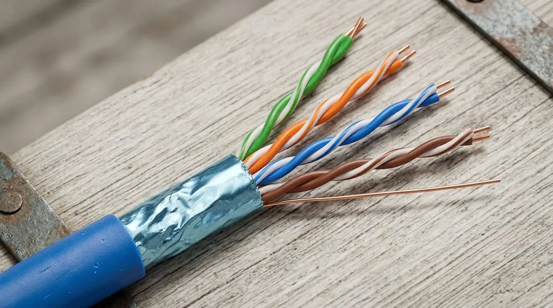
When a cabling project calls for shielded Ethernet cable, selecting the right cable is only the first step. The installed system also needs compatible connectors, patch panels and patch cords, along with a properly implemented path for shield continuity and bonding.
A shielded cable can provide a conductive screen around the twisted pairs, but that screen does not work in isolation. Its effectiveness depends on how the cable is terminated, how the shielding is maintained across connections, and how the cabling system is integrated with the building’s bonding infrastructure.
The first decision is the shielding construction itself. F/UTP uses an overall foil shield, while U/FTP places foil around individual twisted pairs. S/FTP combines an overall braid with individual pair foils. These constructions serve different design requirements, so the appropriate choice depends on the installation environment, the specified cabling performance and the components used throughout the system.
| Designation | Construction | What it means in practice |
|---|---|---|
| U/UTP | No overall shield, no pair shields | The unshielded reference construction |
| F/UTP | Overall foil, unshielded pairs | One foil around all four pairs |
| U/FTP | No overall shield, foil around each pair | Screening at pair level only |
| S/FTP | Overall braid, foil around each pair | Braid over pair foils |
| SF/UTP | Overall braid and foil, unshielded pairs | Two overall layers, no pair foil |
The designation describes geometry, not quality. The letter before the slash is the overall shield, the letter after it is the pair shield: U for none, F for foil, S for braid. A construction with more layers is not automatically the better choice for a given project. The selection turns on the interference environment along the route, the space available in containment and behind the outlet, whether the connecting hardware exists in a matching shielded version, and what the project specification actually calls for. Where a project requires a shielded system, the bulk cable options a supplier can actually deliver in that designation are worth checking before the specification is fixed.
However, selecting a suitable construction does not automatically create a complete shielded channel. The connectors, outlets, patch panels and patch cords must be compatible with the cable and its shielding design. If a termination fails to maintain the intended shielding path, the installed system may not perform as expected.
Maintaining Shield Continuity Across the Channel
Shield continuity must be maintained through the relevant cable and connection interfaces. This requires appropriate components, correct termination practices and a system design that accounts for the conductive path across the channel.
It breaks at the points that are hardest to see. A connector whose shield contact never reaches the foil. A jack whose metal shell is isolated from the cable screen. A shielded horizontal cable terminated with an unshielded plug at one end. A panel where the screen stops at the rear and does not continue to the front. Each of these produces a channel that can pass a wire-map test while carrying a screen with a gap in it.
Continuity alone, however, is not the same as correct bonding. The metallic components of a shielded cabling system must be integrated with the building’s telecommunications bonding infrastructure in accordance with the applicable standards and project design. Bonding establishes the required electrical connection and equipotential relationship between metallic parts. Grounding connects the system to the earth electrode system. The two are related, and they are not the same task.
Which requirements apply is a question about the project, not about the cable. In North America the ANSI/TIA-607 series covers telecommunications bonding and grounding; ISO/IEC 30129 addresses telecommunications bonding networks; regional building regulations add their own conditions. Determining which of these governs a given installation, and what it requires of a panel, a tray or a rack, is work for someone competent to interpret it in that jurisdiction.
Two shortcuts are worth naming. The first is treating the shield as a protective earthing conductor. It is not one, and it must not be used as one. The second is applying a rule of thumb — bond at one end, or bond at both — as if the slogan settled the design. The arrangement depends on the system, the frequencies involved and the standard being worked to.
The opposite assumption is just as unreliable. An unbonded screen is not automatically an antenna that collects every disturbance in the building, and a bonded one does not make a channel immune to interference. What a screen does depends on frequency, on the quality of the termination, on the equipotential conditions and on what is happening around the cable. Screening is one measure among several, and it does not replace separation, routing or filtering at the equipment.
What Makes a Shielded Channel Work as a Complete System
The decisions below are usually made by different people at different times. A consultant specifies, a distributor supplies, an installer terminates, an electrician bonds, and a tester certifies. The channel works when those decisions agree, and fails when one of them is made in isolation.
The first question is whether the project needs a shielded system at all. That is not answered by default, and it is not answered by the category either. Interference environment, target performance, route and the applicable specification decide it, and a project that does not need screening pays for it in cost, termination time and maintenance complexity.
Every component in the channel then has to belong to the same design. The check is not the label on the cable; it is whether the jack, the outlet, the panel and the patch cord are rated for that shielding construction and for that conductor type. A shielded horizontal cable terminated with unshielded hardware does not produce a shielded channel, whatever the bill of materials says.
Termination is where the path is most often broken, and it is rarely broken deliberately. The screen has to be dressed and clamped the way the connector manufacturer specifies, which takes longer than trimming it back. Two habits cause most of the trouble: cutting the foil away because the connector closes more easily without it, and assuming that a metal shell touching a metal panel is a compliant connection.
Bonding then follows the applicable standard and the project design, by someone competent to implement it. It is not a field improvisation, and it is not a substitute for the protective measures of the electrical installation.
Verification closes the loop. A wire-map, a continuity check and a full link certification answer different questions, and passing one does not demonstrate the others. Where the specification requires continuity checks or additional EMC verification, the test plan should say so before the first cable is pulled, because a channel that fails a check added at handover is expensive to correct. The field testing guide covers how test configuration and limits are chosen for the link itself.
These checks are easier to manage when they are part of the original specification rather than left until project handover. For contractors and system integrators, the goal is not simply to install shielded cable, but to deliver a complete cabling system whose components, connections and bonding arrangements meet the intended requirements.
Where Shielded Installations Go Wrong
Choosing the cable without specifying the system is the most common failure, and the most expensive. A bill of materials that names F/UTP or SF/UTP but leaves the jacks, panels and cords unspecified tends to be filled with whatever is in stock. The cable arrives as designed; the channel does not. The correction is to specify the whole channel at the same time as the cable, including the hardware that terminates it.
Mixing components from different designs produces a channel that looks complete and is not. A shielded panel fitted with unshielded jacks, a shielded cable paired with a cord whose plug has no shield contact, an outlet whose metal parts are isolated from the screen — each of these leaves a gap that no cable test reports. Compatibility has to be checked at the level of conductor type, conductor size, termination method and shielding design, not at the level of the product name.
Treating continuity and grounding as one thing produces a system that is neither verified nor correctly bonded. A screen that shows continuity end to end may still be unconnected to the building’s bonding infrastructure, and a panel bolted to a rack is not necessarily bonded to anything. The two checks are separate, and both belong in the specification.
Assuming that shielding is always better is the quiet one. Screening adds cost, termination time and a maintenance obligation: every subsequent move, add or cord swap has to preserve the path that was designed. Where the environment does not justify it, a well-installed unshielded system is the better engineering answer, and saying so is part of the job.
A shielded cabling system is only as effective as its design, component compatibility, termination and bonding. Selecting the cable construction is an important first step, but the finished channel must be treated as a complete system — from the horizontal cable and connecting hardware to shield continuity and the building’s bonding infrastructure.
For a project specification, start by defining the required cable category, shielding construction, installation environment, compatible hardware and applicable acceptance requirements. These details help determine whether a shielded solution is appropriate and how it should be implemented.
WEIHUI CABLES supplies shielded bulk cable in F/UTP (Cat6A) and SF/UTP (Cat6A and Cat7) constructions, along with shielded Cat7 patch cords, and can discuss options against a project specification. Share your target category, shielding construction, installation environment and estimated order quantity to start a project enquiry.