
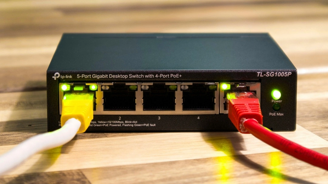
There is no PoE cable.
Power over Ethernet runs over the same balanced twisted-pair cable that already carries the data. IEEE 802.3af, 802.3at and 802.3bt define the electrical interface between the power source and the powered device — not a new cable type. A Cat5e, Cat6 or Cat6A cable that meets its category specification will carry data and DC power at the same time.
What buyers usually mean by “PoE-capable” is narrower and more practical: can this cable carry the required current without overheating, and does it still leave enough voltage for the device at the far end? The answers depend on the conductor, the number of pairs in use, the bundle the cable is installed in, and the connector on the end.
What the PoE types ask of the copper
The standard has raised the available power in three steps, and each step changed something about the cabling behind it. IEEE 802.3bt, published in 2018, is the amendment that pushed PoE past 30 W.
| Standard | Type | Power at the PSE | Power at the PD | Pairs carrying power | Current per pair (typical max) |
|---|---|---|---|---|---|
| IEEE 802.3af (PoE) | Type 1 | 15.4 W | 12.95 W | 2 | 350 mA |
| IEEE 802.3at (PoE+) | Type 2 | 30 W | 25.5 W | 2 | 600 mA |
| IEEE 802.3bt (PoE++, 4PPoE) | Type 3 | 60 W | 51 W | 4 | 600 mA |
| IEEE 802.3bt (PoE++, 4PPoE) | Type 4 | 90 W | 71.3 W | 4 | 960 mA |
Type 1 and Type 2 push current down two pairs — either the data pairs (Mode A) or the spare pairs (Mode B). Type 3 and Type 4 use all four pairs at once, which splits the same job over twice the copper and roughly halves the current each pair has to carry for a given power.
A cable that’s unremarkable at 350 mA can become the weak point at 960 mA. The category rating doesn’t change between those two cases. The current does.
Heat in the bundle is the real limit
A single cable carrying 960 mA per pair runs only a few degrees above ambient. Bundle a few dozen of them together and the picture changes: every cable is now heating its neighbours, and all of that heat has to escape through the outer jacket of the bundle.
The document most installers end up working from is TIA TSB-184-A (2017), “Guidelines for Supporting Power Delivery Over Balanced Twisted-Pair Cabling”. It recommends holding the temperature rise of a fully loaded bundle to about 15 °C above ambient, and it ties the acceptable bundle size to the current per pair, the conductor gauge and the way the cable is installed. Bundle size is the factor that gets underestimated, because the rise grows faster than the cable count does. Route type matters almost as much — an open tray cools, a closed duct or a conduit with no airflow does not. And ambient temperature is already part of the sum before a single cable adds to it, which is how a compliant design in a plant room or an unventilated ceiling void turns into a hot one.
A design that sits close to the limit rarely fails in an obvious way. It holds on a cool morning and drops its device on a hot afternoon, which is exactly when nobody wants to be chasing a fault.
Conductor, gauge, and the voltage-drop budget
Power delivery turns the cable’s DC resistance into a design constraint, because the current makes the round trip and the voltage lost along the way is subtracted from what reaches the device. Two things dominate that resistance: what the conductor is made of, and how much copper is in it.
Solid copper is the reference. Its resistance is what the category specification assumes. Copper-clad aluminium (CCA) isn’t a substitute for it — CCA has higher resistance per unit length than copper of the same gauge, and on a PoE link that extra resistance shows up as more voltage drop and more heating, the two things a high-power device can least afford. Gauge behaves the same way. Heavier 23 AWG conductor loses less voltage over a run than 24 AWG, which is why Cat6 and Cat6A are commonly 23 AWG while some Cat5e and many patch cords are 24 AWG.
The 100 m channel limit doesn’t disappear on a PoE link. The budget is simply shared with the power now: the longer the run and the higher the power, the less of that 100 m you can use before the voltage at the device falls below its minimum. That is the reasoning behind the TSB-184-A recommendation to move to Cat6A for 4-pair 802.3bt power — a conductor and headroom argument, not a bandwidth one.
Shielding is one construction choice that stays out of this calculation. A shielded cable is specified for EMC reasons, and the foil or braid doesn’t add current-carrying capacity — so it won’t rescue a link that is already short of voltage or running hot in a bundle.
Connectors carry the current too
The RJ45 plug and jack sit in the current path, and they are usually the least robust part of it. Repeated mating and unmating under load wears the contacts, which raises contact resistance and adds heat exactly where there is the least metal to absorb it — and the plug is the one component nobody re-tests after installation.
Two IEC standards cover this specifically. IEC 60512-99-001 addresses mating under electrical load; IEC 60512-99-002 addresses unmating under electrical load. Connectors intended for PoE service are tested against them. A plug that was never tested this way can behave at 15 W and misbehave at 90 W.
What to pin down before ordering
If a project has to run more than PoE+ to the far end, these are the points worth settling before the order rather than after a failed commissioning test:
- The highest PoE type the link must support, and whether it will run on 2 or 4 pairs.
- Conductor material and gauge — solid copper, and 23 AWG where high power meets long runs.
- The maximum bundle size and the route it will be installed in.
- The ambient temperature the bundle will see, including the summer peak in an unventilated ceiling or plant room.
- The connector and patch-cord rating against IEC 60512-99-001 and 60512-99-002 for high-power links.
None of these are exotic requirements. They are the numbers a supplier needs to quote a construction that will hold up, and the ones a commissioning test will eventually check — whether or not anyone wrote them down first.